• This forum is strictly intended to be used by members of the VS Battles wiki. Please only register if you have an autoconfirmed account there, as otherwise your registration will be rejected. If you have already registered once, do not do so again, and contact Antvasima if you encounter any problems.

    For instructions regarding the exact procedure to sign up to this forum, please click here.
  • We need Patreon donations for this forum to have all of its running costs financially secured.

    Community members who help us out will receive badges that give them several different benefits, including the removal of all advertisements in this forum, but donations from non-members are also extremely appreciated.

    Please click here for further information, or here to directly visit our Patreon donations page.
  • Please click here for information about a large petition to help children in need.

Indentation Calcs

Yeah I don't really know what can be done from here.

After thinking about it more, I fully agree with DT's comment earlier.
Not gonna comment on new methods for now, as this isn't really what I understand well, but I will say that I generally would assume that a denting calc must use at least:
  1. Something like the area of the dent. (1 cm^2 and 1 m^2 dents should give different results)
  2. Some parameter for how much it was dented. (1cm deep and 1m deep dents should give different results)
  3. Some material parameter. (denting rubber vs denting steel should make a difference)
  4. Some parameter for how thick the dented sheet is. (1mm thick steel plate should give different results from 1m thick steel plate)
Just by my feeling of how the world works.
At a glance, I think the calcs listed above tend to usually not use at least one of those.
I don't know any formula that involves all of those. I can try to construct something from first principles (i.e. selecting a material parameter whose units are in force/m^3), but just converting between different units doesn't guarantee that you'll end up with something correct. I'd like it to be something established elsewhere.
 
Technically Jason's method with the calculator that I used in my calc almost fits the stuff DT said. Problem being, it uses a V bending calculator so it is for a case that is shaped like a V.
Still, it used length of bend, thickness of the sheet and material of the sheet to find the LS and then I used the depth of the bend to find out the energy.
If only the calculator had an explanation on what formula it uses it could be easier.
Here it is btw.
 
Ooh, that does sound like a good avenue of research.
 
There's a link inside that goes to a page with some explanations about the whole thingamajig. That's as far as I will go. I may like calcs but I am no math/physics nerd.
 
Shear stress is only Force / Area. Shear strength itself is 60% a material's UTS.

From there you convert units from pascal - newtons - joules.

Just saying.
 
Another possible avenue is inertia, which can be seen here: https://vsbattles.fandom.com/wiki/User_blog:LIFE_OF_KING/Jujutsu_Kaisen_-_Itadori_throws_a_ball

Sure, a pole is a bit different from a metal plate, but the method behind the madness (indenting) is the same.
I think it could be. Could be also helpful for a calculation I was stumped on with regard to a character rotating the planet 360 degrees (total) on an axis.

That said, in looking it up and even with the example, I'm confused: How would angular momentum (for the moment of inertia) be commonly found?

In looking up inertia, it seems the common formula for such (and the linked wikipedia article) is I = L/w, L being angular momentum, and w being the angular velocity. Additionally, I'm not sure where the "Moment of inertia = pi*(material strength[?])^4/4" is coming from in it. I don't see pi mentioned in anything on inertia.

I could also just be ignorant and not know how a common technique to find angles or something
 
Another possible avenue is inertia, which can be seen here: https://vsbattles.fandom.com/wiki/User_blog:LIFE_OF_KING/Jujutsu_Kaisen_-_Itadori_throws_a_ball

Sure, a pole is a bit different from a metal plate, but the method behind the madness (indenting) is the same.
Moment of inertia is just a way of quantifying how difficult it is to get an object rotating at a certain speed.

I don't know why that would be useful in general (since most feats like these don't involve objects rotating), or frankly, even in that calc (the bending seems to have been caused by the ball's linear momentum, not angular).

If we are to try and use that calc for reference, we'd need to ask the calc's creator for elaboration, since a lot of things in that calc are unexplained or unused.
 
I think it could be. Could be also helpful for a calculation I was stumped on with regard to a character rotating the planet 360 degrees (total) on an axis.

That said, in looking it up and even with the example, I'm confused: How would angular momentum (for the moment of inertia) be commonly found?

In looking up inertia, it seems the common formula for such (and the linked wikipedia article) is I = L/w, L being angular momentum, and w being the angular velocity. Additionally, I'm not sure where the "Moment of inertia = pi*(material strength[?])^4/4" is coming from in it. I don't see pi mentioned in anything on inertia.

I could also just be ignorant and not know how a common technique to find angles or something
Moment of inertia is just a way of quantifying how difficult it is to get an object rotating at a certain speed.

I don't know why that would be useful in general (since most feats like these don't involve objects rotating), or frankly, even in that calc (the bending seems to have been caused by the ball's linear momentum, not angular).

If we are to try and use that calc for reference, we'd need to ask the calc's creator for elaboration, since a lot of things in that calc are unexplained or unused.
Yeah, I had an issue trying to figure out how any of those methods worked as well. Part of it could be the lack of formulae being shown, but still.
 
Formulae aren't shown, numbers are pulled from nowhere, numbers are provided and never used. It's just incomplete as-is.
 
Since the whole thing was never resolved I'm going to explain bending formula.

I am not going to cover the math explaining how it works (Although I can do it in case further explanation is required) but I am going to make a quick guide.

If the bending deformation is plastic the first thing we do is calcutale the plastic section modulus of the object under the deformation. In case the deformation is elastic we use the elastic section modulus. You can find the table here.

The second step is to muldiply the section modulus by the yeild strength of the material. This will give us bending moment - the amount of torque needed to bent the object.

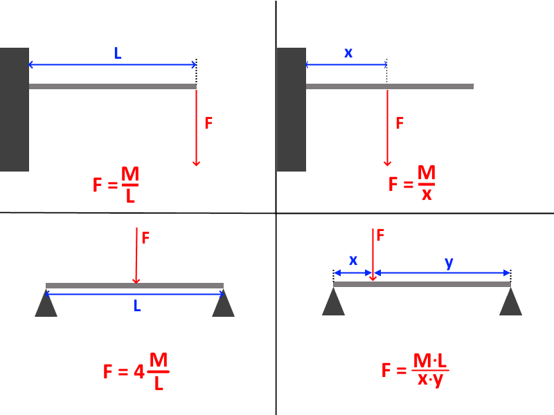
Once we know the bending moment M we can calculate the force F using one of the formulae below depenting on where and how the force is aplied.

latest
 
Last edited:
Technically Jason's method with the calculator that I used in my calc almost fits the stuff DT said. Problem being, it uses a V bending calculator so it is for a case that is shaped like a V.
Still, it used length of bend, thickness of the sheet and material of the sheet to find the LS and then I used the depth of the bend to find out the energy.
If only the calculator had an explanation on what formula it uses it could be easier.
Here it is btw.
This V bending calculator uses the method I've shown above. It assumes rectangular cross section, fully plactic deformation, and 3-point bending (case 3 in the picture above). It also uses ultimate tensile strength instead of yeild strength to get the highest result posible. Yeild strength is generaly much safer
 
Moment of inertia is just a way of quantifying how difficult it is to get an object rotating at a certain speed.
In this context moment of inertia means this. It is used to calculate elastic section modulus. The mass moment of inertia is calculated in a very similar way hence the same name. In fact if we multiply area moment of inertia by density we will get mass moment of inertia where neutral axis turns into axis of rotation
 
Last edited:
Since the whole thing was never resolved I'm going to explain bending formula.

I am not going to cover the math explaining how it works (Although I can do it in case further explanation is required) but I am going to make a quick guide.

If the bending deformation is plastic the first thing we do is calcutale the plastic section modulus of the object under the deformation. In case the deformation is elastic we use the elastic section modulus. You can find the table here.

The second step is to muldiply the section modulus by the yeild strength of the material. This will give us bending moment - the amount of torque needed to bent the object.

Once we know the bending moment M we can calculate the force F using one of the formulae below depenting on where and how the force is aplied.

latest
So, comparing this to the lens of analysis
Not gonna comment on new methods for now, as this isn't really what I understand well, but I will say that I generally would assume that a denting calc must use at least:
  1. Something like the area of the dent. (1 cm^2 and 1 m^2 dents should give different results)
  2. Some parameter for how much it was dented. (1cm deep and 1m deep dents should give different results)
  3. Some material parameter. (denting rubber vs denting steel should make a difference)
  4. Some parameter for how thick the dented sheet is. (1mm thick steel plate should give different results from 1m thick steel plate)
Just by my feeling of how the world works.
At a glance, I think the calcs listed above tend to usually not use at least one of those.
It definitely seems to include 2 (with F in the last step), and 3 (with the yield strength in the second step), but seems to either be missing part of 1 or 4 (with the cross-section of the material in the first step), in exchange for including an extra occasionally-relevant detail (how far away the point of contact is from an immutable anchor point).

As such, I think it would end up being insufficient for our purposes.
 
Yes, unfortunately this formula only works for bending long poles or flat sheets across their entire length. I have absolutely no idea or how to calcute a randomly shaped dent on a flat sheet
 
Better than nothing I guess, but it's something that should be applied with care.
 
Since the whole thing was never resolved I'm going to explain bending formula.

I am not going to cover the math explaining how it works (Although I can do it in case further explanation is required) but I am going to make a quick guide.

If the bending deformation is plastic the first thing we do is calcutale the plastic section modulus of the object under the deformation. In case the deformation is elastic we use the elastic section modulus. You can find the table here.

The second step is to muldiply the section modulus by the yeild strength of the material. This will give us bending moment - the amount of torque needed to bent the object.

Once we know the bending moment M we can calculate the force F using one of the formulae below depenting on where and how the force is aplied.

latest
Is it good that I calculated it this way?
 
No, the formulas presented here don't work. While the rod is seemingly held with five points of contact, the bending clearly happens independent of those. It doesn't correspond to any of those situations listed, with the fulcrum being a part of the hand
 
No, the formulas presented here don't work. While the rod is seemingly held with five points of contact, the bending clearly happens independent of those. It doesn't correspond to any of those situations listed, with the fulcrum being a part of the hand
Ugarik asked me to use the 4th formula, but do you have any idea?

TheRustyOne told me to find the whole area and multiply by 208.

Will this work?
 
Neither of those will work.

The fourth formula involves there being two set points, with a force applied partway between them. In this case, the set points weren't actually holding it down (and if they were, there's five), so none of those formulas are applicable.

Multiplying the whole area by 208 is nonsense, as discussed in this thread.

@Ugarik @TheRustyOne
 
I have nothing to add beyond acknowledging the discussion here.

Knew I should've just ignored any kind of indention calcs period, they've always been a headache.
 
Neither of those will work.

The fourth formula involves there being two set points, with a force applied partway between them. In this case, the set points weren't actually holding it down (and if they were, there's five), so none of those formulas are applicable.

Multiplying the whole area by 208 is nonsense, as discussed in this thread.

@Ugarik @TheRustyOne
Do you have any idea which formula I should use?
 
Do you have any idea which formula I should use?
As discussed above, we have not found one that works for feats like that.
 
Do you have any idea which formula I should use?
Okay so in this case we have two forces aplied in the opposite directions y distance appart from each other like in the picture below:


Since both F1 and F2 are aplied by a single hand they have to be equal due to Newton's third law.

In order to find the bending moment M we have to figure positive torque at any point where force F is applied.
Since the only positive torque component at that point is Fy. The formula is just M = Fy.

Solve for F and we get F = M/y.

Kind of funny it turns out way easier than simple 3 point bending like in case 3 since I don't have to calculate net torque and solve for either N1 or N2
 
I don't think that works since that still involves two fixed points on the end of the rods, that can counteract the force applied, which is clearly false.
 
I don't think that works since that still involves two fixed points on the end of the rods, that can counteract the force applied, which is clearly false.
Yes. Negative and posive torque components do counteract. In fact they are equal in magnitude and thefore make net-torque zero.

But it doesn't mean the rod it not under bending load. It just means that it's not rotating as the result of all those forces.

The bending moment calculated from section modulus and yeild strength just gives us the maximum bending moment the road can support without deforming. So we only need to find torque that acts on either positive (anti-clockwise) or negative (clockwise) direction on the rod at the point where force is aplied.

As you can see in the picture above, the only force that wants to rotate the rod clockwise is F2. Wherefore bending moment is F2*y

I do agree that the result seems counter intuitive. After all it means that the force is independent on the length or the rod as well as the position of the hand but I can proof that I did not mess anything up if you think it is necessary
 
Specifically, my concern is that both N1 and N2 are not represented in that feat, and so the model is not valid for that situation.
 
In that case we can define bending moment M as counter-clockwise torque at that point.

M = N1*x+N2*(y+z).

Force F is not in the equation since it acts in the opposite direction.
In statics sum of all forces acting on the rod has to be zero, otherwise it would accelerate in the direction of the net-force.

F1-F2+N1+N2 = 0

Since F1 is equal to F2 they cancel out and we get

N1 = -N2

Net torque also has to be zero otherwise the rod would start rotating. We can express net torque at the left fixed point as:

F*x - F*(x+y) + N*(x+y+z) = 0

(Take a note that since the net-torque is zero, we can express net forque at any arbitrary point on the rode. In wouldn't affect the result. I chose the left fixed point pretty much randomly)
Now we can solve for N and we will get:

N = F*y/(x+y+z) or N = F*y/L where L is length or the rod.

Now replace both N1 and N2 in the first equation with F*y/L

M = F*y*x/L+F*y*(y+z)/L
.

If we simplify the equation we'll get M = F*y*(x+y+z)/L and since L = x+y+z, M = F*y

The whole thing was mostly redundant but it feels more complete and I ended up with the same result F = M/y
 
In that case we can define bending moment M as counter-clockwise torque at that point.
Can you elaborate on how that resolves the issue?
 
Positive and negative torques acting on the rod are equal in magnitude as long as the rod is static. So it doesn't mater if we chose those that act in clockwise or counter-clockwise direction.
 
How does that resolve the issue of the formula involving fixed points at the end of the rod, despite the feat in question not seeming to have such fixed points?
 
The hinges act as support points. The fact that the rod is longer doesn't affect the result

 
I don't think they do; we see the rod being held between them, we see the main focuses of the crumpling within the hand, and the far larger thickness of the rod compared to those hinges necessitates that the rod is stronger; and so if they were truly acting as supports, they would've been bent, not the rod.

Unless we assume that they're different materials (very unrealistic given how they're drawn in the exact same way), or that the rod is more hollow (very unrealistic given how the rod is drawn, and would make this sort of LS calc invalid anyway).

And as said earlier, even if we grant all that, the little bit sticking out the bottom seems like it would complicate things beyond the simple model provided.
 
Back
Top